Shell Creation
Translated Document
This document has been translated from the original Japanese by members of the Ukagaka Dream Team community.
To see the original document, click here.
To submit corrections/updates, see our repository to open an issue or find where to contact us.
This page describes the basic shell creation process.
Please note, however, that this page mainly focuses on the contents of the settings files, and hardly touches on drawing or image processing.
See also the shell file structure.
Prepare an image
First, prepare an image to be displayed on the desktop.
You can either draw your own image, or use a ready-made shell that has been distributed, called a freeshell.
The default image format for ghosts is png.
jpg, bmp, etc., cannot be used (except in SSP).
If png is used, there are no restrictions on size or the number of colors, but transparency is invalid. (In SSP only, it can be enabled depending on the settings. See below section About translucent surfaces).
If you want to reduce file size, use a tool to optimize the color.
Each of the images that make up the shell, as well as each frame of animation as described below, is managed as a unit called a surface.
Surfaces can be created by preparing an image named "surface*.png" (where the "*" part is a number greater than or equal to 0), or by combining multiple images in surfaces.txt as described below.
surface0.png and surface10.png are mandatory for basic use.
surface0.png is the basic surface for the main character side, and surface10.png is the basic surface for the partner character side.
Even if you only have one character as a ghost and do not need a partner character, please prepare a single-color, filled-in image (which will be displayed completely as transparency, see below) as surface10.png
Surfaces can be written as surface0000.png, surface0010.png, etc., and will be recognized as surface0.png, surface10.png, etc.
In the surface image, the pixel at the upper left corner is displayed as a "transparency color".
If the same color as the transparency color is also in the character, that area will also be transparent, so use a color that is not used in the character for the transparency color.
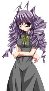
If you prepare your own images to be used as surfaces, one feature to be aware of is the handling of outlines.
 |
→ |  |
As a result of the character's outline becoming translucent and blending with the background, it will appear as shown on the right.
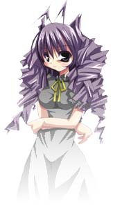
 |
→ |  |
If the outline is not mixed with the background, like this, the color will be removed cleanly.
Write descript.txt
The file descript.txt is used to set up basic information about the shell.
If the descript.txt is not prepared properly, the shell will not be recognized by the ghost.
For now, copy and paste the following into a text file named descript.txt and rewrite it as appropriate for your shell.
charset,UTF-8
type,shell
name,Name of this shell

craftman,Name of the author (please write in alphanumeric characters only)
craftmanw,Name of the author (can be written in any characters)
craftmanurl,URL of the author (e.g., distribution site URL)
In basically all cases, the charset should be UTF-8. (Translator note: The original document recommends SHIFT_JIS, but as this is only suitable for developing ghosts in Japanese, it has been replaced with UTF-8 in this translation. UTF-8 is the recommendation for all international ghosts.)
There are many other items that can be set, but the above are the minimum required (strictly speaking, only name and type are required).
For settings not covered here, and more detailed descriptions of each setting, see the "Shell Settings" page.
As an example, to change the default balloon position for the entire shell, you will have to add the following items:
sakura.balloon.offsetx,0
sakura.balloon.offsety,0
kero.balloon.offsetx,0
kero.balloon.offsety,0
sakura.balloon.offset changes the balloon position on the main character's side, and kero.balloon.offset changes the balloon position on the side character's side.
If you increase the number, higher X coordinates will display the balloon closer to the character, and higher Y coordinates will display lower.
Adding a minus symbol reverses the display position, so that negative X values are displayed further away from the character, and negative Y values are displayed higher up.
If you would like to display the menu with the dressup items, you must also put the description of these in the descript.txt file, but please see the page on setting up dressups for an explanation of how to do this.
Write surfaces.txt
First, create a text file named surfaces.txt.
This is the file for setting up animations, compositing images, and setting up collision areas for manipulating the character with the mouse cursor.
See also the page "Shell Settings - surfaces.txt".
After creating surfaces.txt, first copy the following at the top.
charset,UTF-8

descript
{
version,1
}
The first line specifies the same character coding as in descript.txt. If there is no particular reason to use another charset, UTF-8 is fine. (Translator note: As in the previous section, the original document recommends Shift_JIS. Since Shift_JIS is only suitable for Japanese ghosts, UTF-8 is recommended in this translation.)
Below that is a description of the format of the animation settings.
If this description is missing, the animation settings must be written using the old definition (SERIKO/1.x).
Note that the examples that appear below on this page are based on the new definition (SERIKO/2.0).
Write surfaces.txt - Collision section
Let's start by defining a collision area on the surface.
First, add the following to surfaces.txt.
surface0
{
}
This would mean something like, in these braces ({} braces) are settings for surface0.
This is not only for collisions; the animation and element settings that are covered later will also be written in this section.
If you write the following here, it will define a collision area.
surface0
{
collision0,117,71,185,130,Face
collision1,115,174,174,217,Bust
}
As shown above, write collision0, collision1, collision2, in order for each collision area.
Make sure that the numbers are unique within a single surface.
The maximum number of collisions per surface is 256.
The four numbers after that are coordinate specifications.
The sequence of coordinates is the upper left X and Y coordinates, then the lower right X and Y coordinates. The upper left corner of the surface image itself is 0,0.
The last string will be the name of the collision area to be used on the ghost side.
Note that you can set collision areas with the same name (names such as Face and Bust in the above example) multiple times. (For example, if you want to set a collision area with the name Hand, in most cases the areas will be separated for left and right hands. Therefore, the collision definition for Hand will also have to be split into two lines.)
Write surfaces.txt - Animation section
Animation in ukagaka (called SERIKO) is expressed by drawing a series of still images.
Here is a brief introduction on how to set the timing of the animation execution, how each still image overlaps, etc.
Below is an example of making surface0 blink to illustrate animations.
surface0
{
animation0.interval,sometimes
animation0.pattern0,overlayfast,100,50,0,0
animation0.pattern1,overlayfast,101,50,0,0
animation0.pattern2,overlayfast,100,50,0,0
animation0.pattern3,overlay,-1,100,0,0

collision0,117,71,185,130,Face
collision1,115,174,174,217,Bust
}
To animate surface0.png, write surface0 like this, and define the animation content in the braces ({} braces) below it.
animation0.interval,sometimes
The line that starts with animation*.interval defines when the animation with that number will be executed.
The number after the word "animation" is the ID of the animation definition (the timing settings (interval), and subsequent "frame" settings (pattern, etc.))
Animation IDs can be any number and do not have to be sequential, but it is expected that animations with the same meaning will be given the same ID※.
The "sometimes" following animation0.interval is the content of the interval definition.
If sometimes is specified, as in the example, the animation will run on its own occasionally (With a chance of 1/2 per second).
In other words, you are specifying something like "the animation with ID 0 sometimes runs on its own".
See the section on animation intervals in "Shell Settings - surfaces.txt" for what other timing specifications are available.
This is followed by the definition of each still image (frame) that makes up the animation.
Write each pattern in order: pattern0, pattern1, pattern2, and so on. Pattern numbers cannot be omitted or duplicated.
Do not forget to put the ID (animation*) of the animation group at the beginning.
Also, the interval definition line and the series of pattern definition lines should be written consecutively, not in separate places.
animation0.pattern0,overlay,100,50,0,0
The overlay part specifies the drawing method.
Overlay is a drawing method that overlays an image on top of the original image.
Various other drawing methods are also available.
For details, see the section on surface drawing methods in "Shell Settings - surfaces.txt".
animation0.pattern0,overlayfast,100,50,0,0
The 100 part means that surface100 is what is drawn in this frame.
Basically, you can think of it as surface100.png.
If you specify 101, surface101.png is used.
A value of -1 will stop drawing the animation and reset the display to the base image (surface0 in the above example).
animation0.pattern0,overlayfast,100,50,0,0
The 50 part is the display time (unit: milliseconds).
Please specify the time until it switches to this frame.
Note that it is not the display time of the frame itself.
animation0.pattern0,overlayfast,100,50,0,0
The last 0,0 part is the display position of the frame (X coordinate, Y coordinate).
This specifies how much to shift the image from the original image's position.
Positive X values move towards the right direction, and positive Y values move downwards.
Write surfaces.txt - element synthesis section
element is a mechanism for combining images made of multiple parts and treating them as a single surface.
For example, if all surfaces must be prepared as images such as surface0.png, then if you want to add more facial expressions to a character, you must prepare as many full-body images as there are facial expressions, even if the only difference is a slightly different mouth shape.
However, if it is possible to separate body parts and facial expression parts and composite them, then even if you want to add more facial expressions you will only need to prepare images with the different facial expressions. Thus, the overall shell size will be reduced considerably.
Furthermore, if the eye and mouth parts are separated, you can create expressions by combining different eyes and mouths without having to draw the full expression itself.
The following is an example of an element definition.
surface1
{
element0,overlay,body0.png,0,0
element1,overlay,face1.png,0,0
}
Now "face1.png" overlaid on top of "body0.png" is defined as surface1.
You can add as many parts as you want to overlap.
In this case, surface1.png is not necessary.
element0,overlay,body0.png,0,0
The number immediately following "element" is the ID (serial number) of the element on this surface.
IDs are sequential numbers starting from 0. The smaller the number, the lower (at the back of the screen) the part to be composited.
Note that a png image with a name like surface*.png is considered to be a part below element0.
element0,overlay,body0.png,0,0
The keyword that follows is the drawing method.
It is basically the same as in animation, but some methods that do not purely combine images, such as "start" and "move", cannot be used.
element0,overlay,body0.png,0,0
Specify the name of the file to be composited.
A png file with any name can be specified.
element0,overlay,body0.png,0,0
The last two numbers specify the composite position (X coordinate, Y coordinate).
This specifies how much the image should be shifted relative to the base image for compositing.
Positive X values move towards the right direction, and positive Y values move downwards.
By the way, in this example, unlike the previous collision area and animation sections, the elements are defined on surface1 instead of surface0.
Although we are only talking about examples, there is a reason for this※.
When considering only the behavior of the shell (ghost) itself, there is no problem with using elements on surfaces 0 and 10.
Write readme.txt
If there is a file called readme.txt, it can be displayed in the owner draw menu, or during installation.
Although it can be omitted, if the ghost author and shell author are different, it may be a good idea to include contact information.
Please fill in a description of the shell, contact information, and other necessary details.
Like other files, readme can also use charsets other than Shift_JIS if you write "charset,UTF-8", etc., on the first line, or include BOM.
About translucent surfaces
To make an image translucent, create a "pna" file with the same filename as the image you want to make translucent.
For example, surface0.pna will be used for surface0.png.
In SSP, it can also be prepared as a part of element composition. For example, face1.pna will be used for face1.png.
pna is simply a renamed png, which represents transparency in grayscale.
In a pna, completely white areas are opaque, completely black areas are transparent, and areas that are in between are translucent.
 |
→ |  |
→ |  |
| surface0.png | surface0.pna | Desktop display |
Translucent areas are clickable as part of the character.
Therefore, transparent areas should be completely black (RGB=0,0,0).
In the case of SSP, you can create a surface*.png as a PNG with an alpha channel and use that alpha channel as the transparency, without using pna.
In that case, the following statement must be added to the descript.txt file:
seriko.use_self_alpha,1
For details on how to create a PNG with an alpha channel, please refer to the instructions for various painting software (some software may not be able to handle it. Try searching for keywords such as PNG, 32bitPNG, αPNG, etc.).
Network updates for additional shells
SSP allows you to add netword update functionality to the shell itself.
For more information, please read the "Support for Network Updates" page.
About dressups
In ukagaka, dressup is set up as a type of animation.
For more information, please read the "dressup settings" page.
Consolidating settings common to multiple surfaces
For example, if there are several surfaces with the same character posture, there may be surfaces with exactly the same collision areas, animation specifications, and so on.
In such cases, there are several convenient ways to write the settings besides copying and pasting the same settings over and over again for each surface brace.
However, most of these methods are SSP only.
For more information, see "ID specifications possible for surface* braces" in the "Shell settings - surfaces.txt page.
Owner draw menu settings
The background image and text color of the owner draw menu (right-click menu) can also be set in the shell.
For more information, please refer to "Owner draw menu settings".
Thumbnail image settings
The shell selection in the owner draw menu allows thumbnail images to be displayed when the cursor is hovered over a shell.
It is recommended to prepare a thumbnail when there are multiple shells and you want to make it easy to identify them at a glance.
If an image called thumbnail.png is in the same folder as the shell, it will be used automatically.